Make my freezer smarter (Part 2)! Now featuring the ESP8266 :D

If you read my previous post, I’ve been on a journey to make my freezer smarter. As it turns out, freezing a SmartThings ZigBee Multisensor tends to destroy CR2450 batteries. I’m sure that, coupled with the continuous temperature rise and drop contributed to this solution not working for me.

After doing EXTENSIVE searching for the “right” solution, I found a few battery powered options.  I wanted something hardwired to power, with a waterproof temperature sensor.  To my surprise, this product category did not exist.  So I set out to make my own solution.

My goal here is to show you everything you need to know about making a ESP8266 Wi-Fi node that communicates via MQTT and/or directly publishes to a SmartThings HUB.  I’ll share the hardware, schematics, code, and some pictures of the finished product.

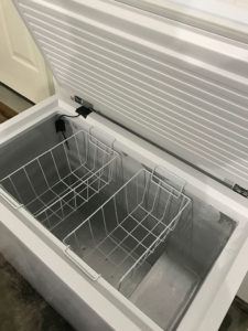
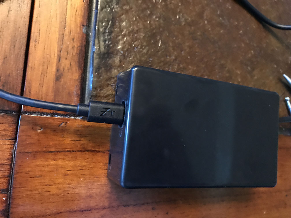
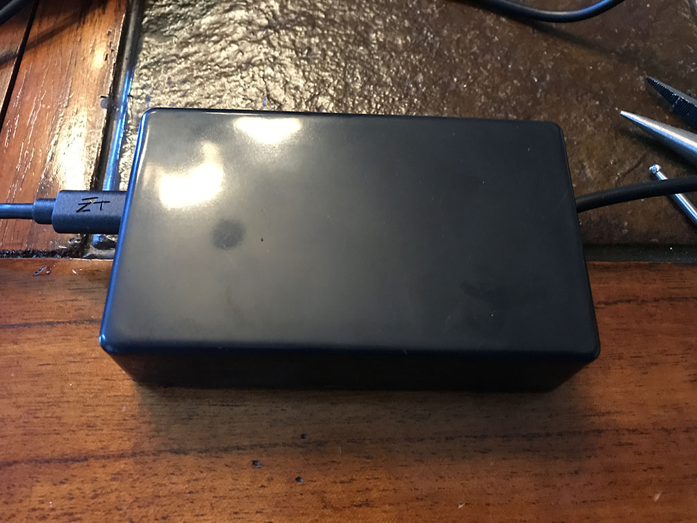
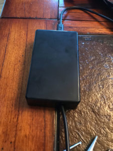
Here are a couple of pictures of the finished product. If this interests you, read more after the break.
 

Continue reading…!

Shopping!

Time to go shopping!  I know I wanted to try out an ESP8266 after seeing the multitude of cool projects done with it.  Plus the development kit is only $8-9 USD.  Why not?

Shopping List:

Total Cost: $78.29

Now, there are a lot of parts on the list above you might already have, or might find in lower quantities. I actually wanted some extra of everything for upcoming projects (Stay tuned!). BOM cost for this project will be around $21.65. That isn’t too bad IMHO.

Other stuff (if you don’t already have these), just to make life easier:

Total Cost: $89.81

You may also want some standard electronics equipment like a multimeter, pliers, ESD protection, oscilloscope, etc. These aren’t totally required for this project.

Schematics

This is going to be pretty easy.  The ESP8266 is doing all of the heavy lifting for this project.  Having the development kit takes care of DC voltage regulation, USB serial, WiFi, and the code space to make it do your bidding.  All we need to do is wire up the DS18B20.

The DS18B20 is a 3 wire interface.

  • Red is your supply voltage (VDD) from 3.0V to 5.0V.  For this, we are going to take power from the ESP8266 off one of the 3.3V voltage pins.
  • Black is your ground (GND).  For this, we are going to take ground from the ESP8266 off one of the GND pins.
  • Yellow is your 1-Wire serial interface (DQ) for communicating with the sensor.  For this, we are going to wire this to one of the GPIO’s on the board.

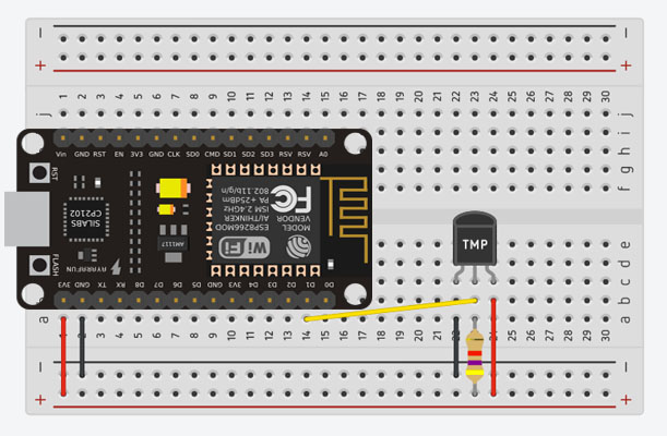
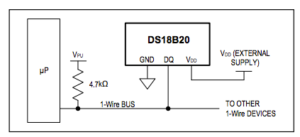
Wiring up this sensor is pretty straight forward, but there is one thing you will need to do to ensure proper communications over the 1-wire serial interface.  You will need to make sure you install a pull-up resistor (4.7kΩ) on the 1-wire serial interface (Yellow) above as shown in this diagram from the datasheet.  Here is a schematic of how this looks.
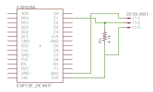
For this example, here is a snapshot of our planned schematic.

And here is how it will look on our breadboard

Time for some real work!

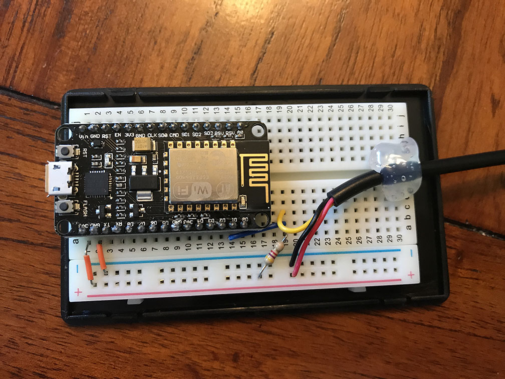
Now it’s time to wire this guy up.  Here are some photos of the project.  (Note: This project can easily be done sans breadboard by soldering directly to the pins on top of the board.  I chose to use a breadboard mostly because I had the space in my box.  Your choice here on what path you want to take!)

Some “Next Level” Dremel work here…

Annndd.. A glamor shot

Let’s write some code! [Coming Soon]

I recommend taking the device out of the box before starting this.  Getting to see the LED status is very handy as you start downloading code and testing.

[Will post the code once I get it up on my git repo.]
Make my freezer smarter (Part 1)!

About a month ago, I went out into the garage to grab some hamburger meat for dinner. As I opened the deep freezer in the garage I was immediately slammed with a horrific odor. That’s right, worst case scenario, for some reason my garage freezer was at room temperature and everything was ruined. This is the second time in 6 months this had happened. Both times the GFCI popped in the garage (for reasons unknown), which caused power to be cut to the deep freezer. Massive loss of about $350 worth of meats and other frozen foods.

Thus begins my journey to make my deep freezer smarter.

Step one was to determine root cause (why did the GFCI Pop?)

Well, this is a simple note to anyone moving into an older home with GFCI outlets. Older outlets can wear out over time if they have been popped multiple times. Easiest fix is to first replace the outlet.

I wanted to go with a Z-Wave GFCI outlet to monitor with SmartThings, but to my surprise, this product doesn’t exist! Sure I could add a smart plugin outlet and maybe monitor power, but you kind of need something with a backup battery. Even if I installed this, I still would not know if the freezer was getting cold.

So the first step was to buy a new GFCI outlet. I ended going with this one, which has an audible alarm. I figured an audible beep is better than nothing, even though we wouldn’t be able to hear this beeping from inside the house.

Next, I decided to go an entirely different route.  Let’s monitor temperature.  Easy enough.  Find a Z-Wave/ZigBee sensor that works in a freezer, drop it in there, setup SmartThings, notify me when it goes above a certain temp.

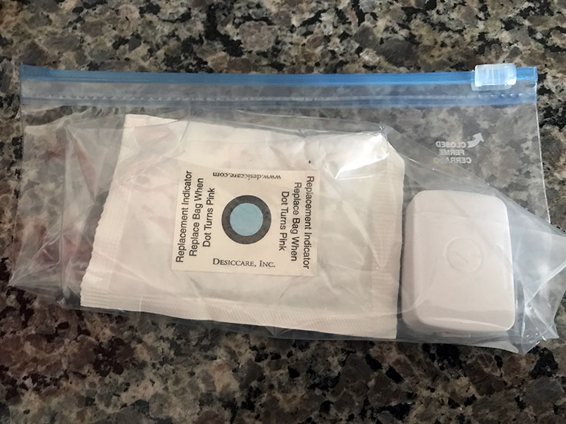
After reading about some success stories of people using a SmartThings ZigBee MultiSensor for this purpose in a deep freezer, I decided to give it a shot!  Why not right?  So I picked up one from Amazon, dropped it in a moisture tight freezer bag with a desiccant pack, put this in the freezer and set myself up to monitor freezer temps.


EASY PEASY, until day 2….

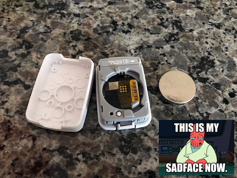
Now, I have around 5 of these MultiSensors doing various things in my house.  Battery life is terrific…lasting roughly 6 months or longer depending on the application.  I immediately noticed battery life plummeting on this sensor.  Fast forward 2 weeks later, and I’ve now gone through three 2450 coin cell batteries.

Some background on deep freezers and compressor applications.  Unlike a regular outdoor temperature or inside temperature, a deep freezer actually swings in temperature (quite dramatically) from -15F to -9F before the compressor turns back on to lower it back to -15F.  Your temperatures may vary, but you get the idea.  The MultiSensor is designed to capture 1F changes in temperature and report.

My immediate thought was – mmkay, so it’s reporting too much, killing my battery.  I rewrote the stock groovy file for the MultiSensor to just focus on temperature and only report every couple of hours.  I was going to link that here, but who cares, it doesn’t work.  Battery still dies in 2-3 days.

Even though the batteries are specced for this temperature range, these devices simply eat batteries at temperatures below -10F.  I even did research on 2450 batteries and chose a brand that was specced down to an operational range of -30F.

The sensor works great, but I can’t replace batteries weekly in this thing.  So I thought – maybe hardwire the sensor to power, solder in a 3V PSU and go for it.  I almost immediately changed my mind.  The only thing worse than a moist deep freezer is having live voltage running into it from a DC power supply in a GFCI outlet.  Shot this idea down before I started.

Okay easy enough, I’ll find a Z-Wave, ZigBee, of Wi-Fi device with an external waterproof temperature sensor.  No dice, can’t find one.

So now I’m back to the drawing board.  Here’s my gameplan.  I’m going to buy a NodeMCU ESP8266 and a DS18B20 Waterproof sensor.

Shopping List:

Total Cost: $78.29

Now, there are a lot of parts on the list above you might already have, or might find in lower quantities. I actually wanted some extra of everything for upcoming projects (Stay tuned!). BOM cost for this project will be around $21.65. That isn’t too bad IMHO.

Other stuff (if you don’t already have these), just to make life easier:

Total Cost: $89.81

You may also want some standard electronics equipment like a multimeter, pliers, ESD protection, oscilloscope, etc. These aren’t totally required for this project.

Next Post (Part 2) will detail this DIY build and code examples.  I plan to integrate this directly with my SmartThings HUB to report temperatures in real time!


New Host for my Lab!

I recently picked up a new host to add to my home lab.  For years, I’ve been running VMWare ESXi/VSphere on a single node. Recently the RAM utilization was starting to creep up to the point where I couldn’t squeeze any more VMs on it. I started out on a month long deal-hunt to find something that would work for me.

My requirements were:

  • Cheap (like real cheap!) <$300 preferred
  • Relatively modern CPU architecture (at least 4-cores, 8 logical)
  • Power Bill Friendly (Energy Efficiency for performance)
  • Preferably rack mounted
  • At least  32GB of RAM
  • Quiet if possible!
  • Some type of remote management
  • Support for remote monitoring (SNMP/iDRAC/etc).
  • Dual GB NIC with room to add a NIC card

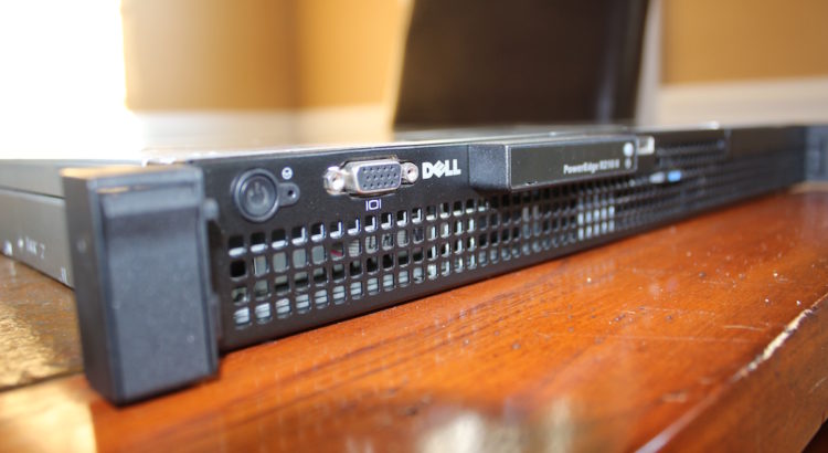
I ended up scoring a used Dell R210ii.  This ticked off nearly everything on the list.  Here are the specs!

  • Intel Xeon Quad Core E3-1240 v2 3.4GHz
  • 32GB DDR3 1600MHz (Maxed out)
  • 240GB SSD
  • Dell iDRAC 6
  • Dual GB NIC + Management port

All in shipped price of $285

Read more… Pictures included!
Read More